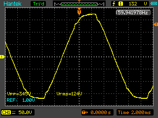
I just installed a UPS the other day (an older Back-UPS XS1300, pictured) and noticed on the back it’s an “approximate sine wave” output. After reading the bottom closer, it’s specified that the device, under 25% load, has a THD of 55% and a maximum harmonic amplitude of 43% of the fundamental’s amplitude. Sounds pretty bad, but what does that really look like?The answer is that it looks just awful. For reference, let’s look at what the wall is putting out.

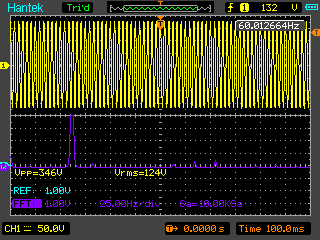
Seeing that, I thought, eh, could be better. Generally clean looking sine wave, not quite sure what the chop is there on the trailing edge, but whatever. At least it looks alright. Looking in the frequency domain, it looks pretty clean as well:

Maybe the frequency peak is wider than it could be, but I don’t really know quite what to expect here anyway, so whatever. Looks good.
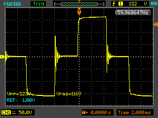
Okay, so what about this ‘approximate’ sine wave?

I’ll take pulsed square wave with a side of aggressive ringing, please! Of course, designing a proper sine-output inverter would add a fair bit of cost. But jeez, I didn’t expect that ringing, anyway! Maybe it’s got something to do with my probe termination, I’d expect overshoot on a low-impedance load to be lower. But I did have maybe 80 watts of load on during this measurement, so that much ringing from just probe impedance mismatch seems odd.

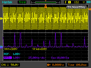
Of course, the frequency domain looks insane as well. Talk about ugly! Of course, most devices will tolerate this. For basic things like lightbulbs, it’s totally irrelevant. Taking measurements with a high-quality TRMS meter, the output does drop from 120nom in to 115nom out. But I certainly wouldn’t want to run any expensive equipment on battery from this thing for too long! Probably a good way to toast CFLs too.

Be First to Comment